The final project must include:
1. 2D and/or 3D designed part(s)
2. subtractive manufacturing (i.e. cnc) part
3. may include:
-->molded or cast part(s)
--> 3d printed part(s)
-->laser cut part(s)
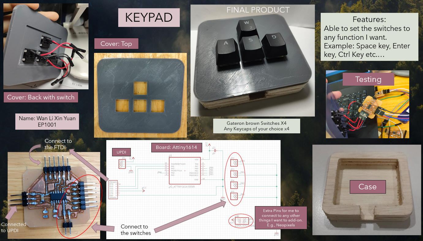
4. an embedded microntroller that you designed & fabricated
5. input and/or output device(s) that interacts with the user
embedded program
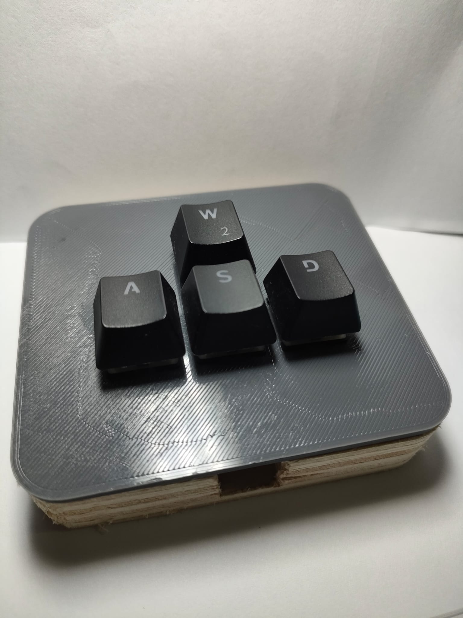
For my final project I have decided to create a keypad that allows me to play my favourite game Tetris. As my current keyboard do not have the arrows key for me to play Tetris and have some spare switches lying around at my house. This keypad will have a total of 4 keys
| Item | Quantity |
|---|---|
| ATTiny1614 | 1 |
| Gateron Brown Switch | 4 |
| Keycaps | 4 |
| 1uF capacitor | 1 |
| Headers | 8(switches), 6(FTDI), 3(UPDI) |
| Female Jumper wires | At least 15 |
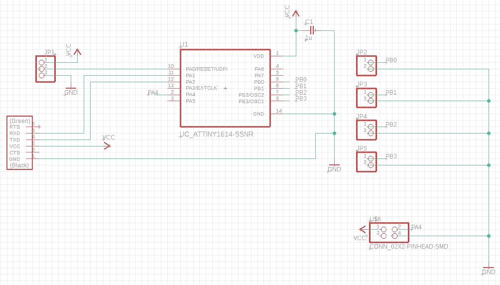
One of the problems I faced when making the PCB board is deciding on which chip to use. After consulting Mr Steven, he recommend me to use the ATTiny1614 since that only have 4 switches. After putting in the headers for the switches I decide to put one 2x2 pinhead in case after making the board I want to add more stuff onto the board.FTDI and UPDI pins are added as I will using them when coding. After arranging everything in order below is how the final circuit will look like.
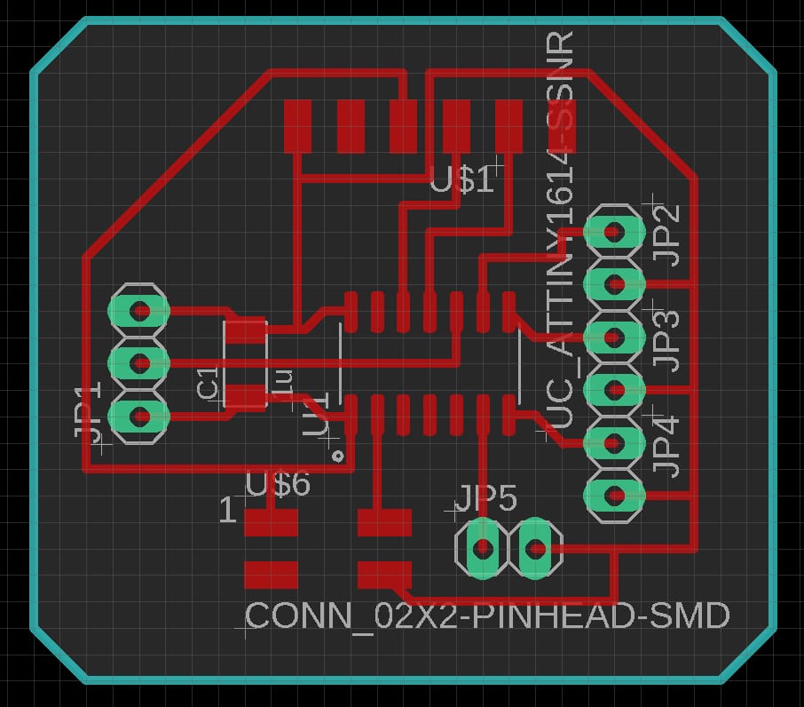
I then convert into the schematic board and start arranging it so that all the wires are connected correctly.
Using Gimp to fill up the padholes and change the inside of the outline to white
| Tracekeypad | 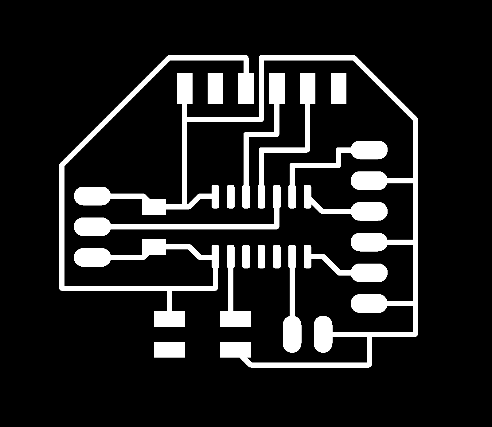 |
|---|---|
| Outlinekeypad |  |
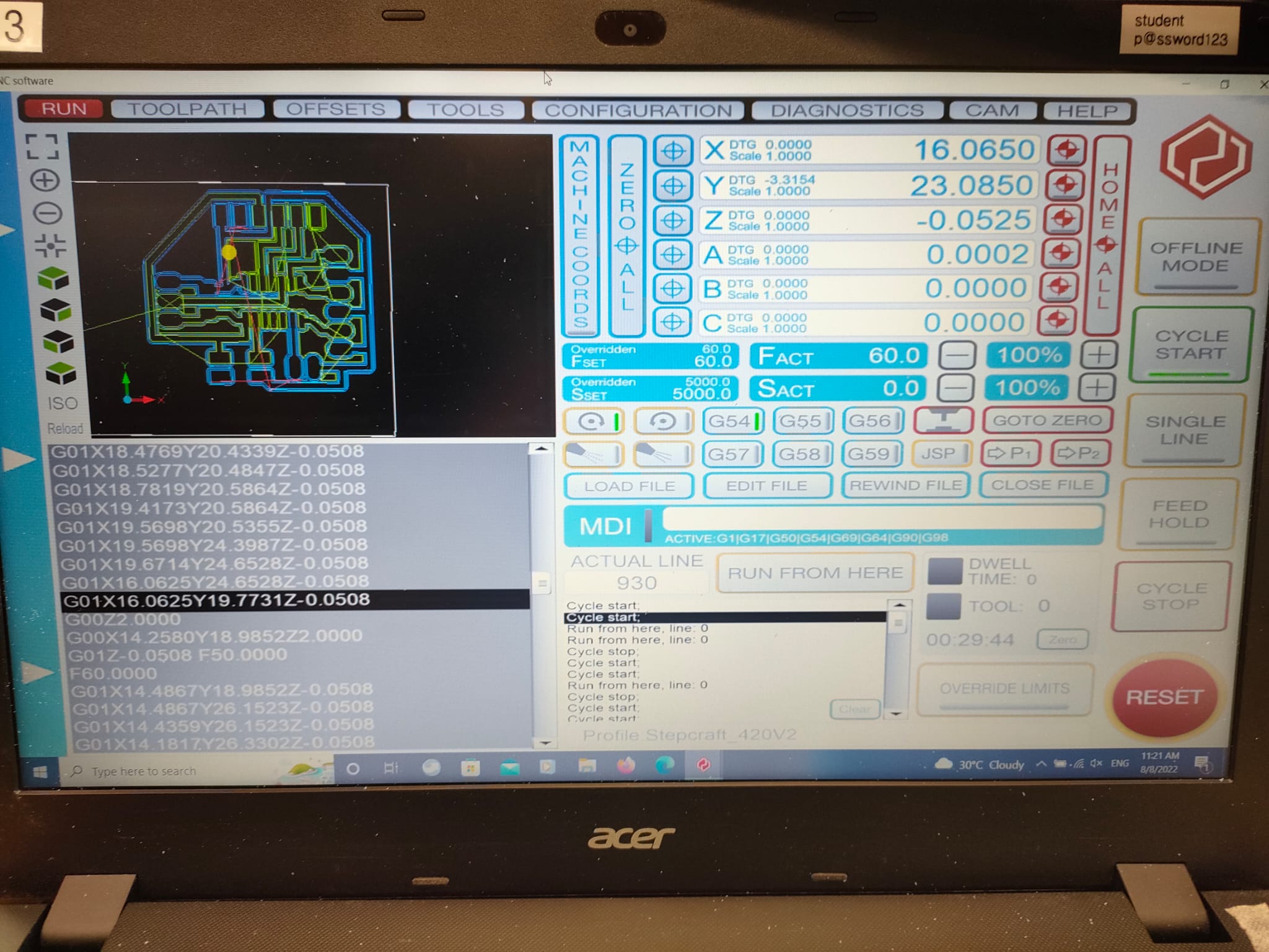
After Importing the image in gimp, I can use the mod software to generate the G-code and save it in my thumb drive than then load it into Stepcraft420
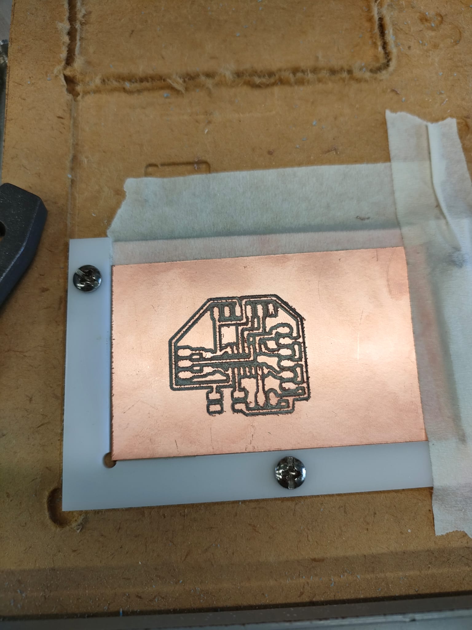
| Trace cutting | 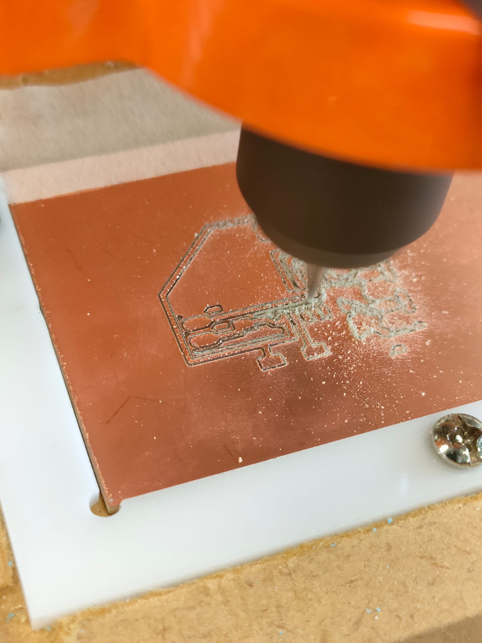
Video |
|---|---|
| Outline Cutting | 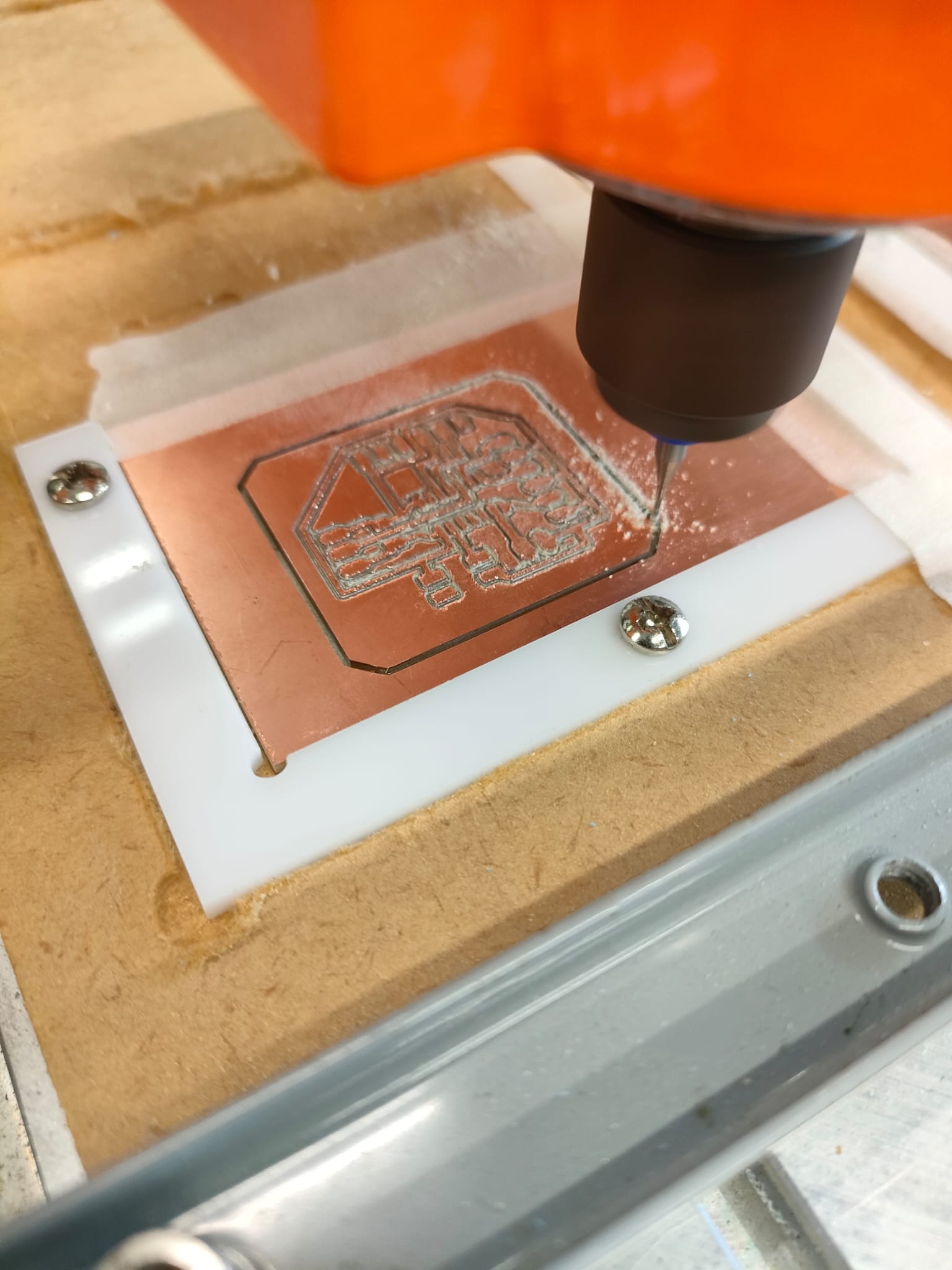
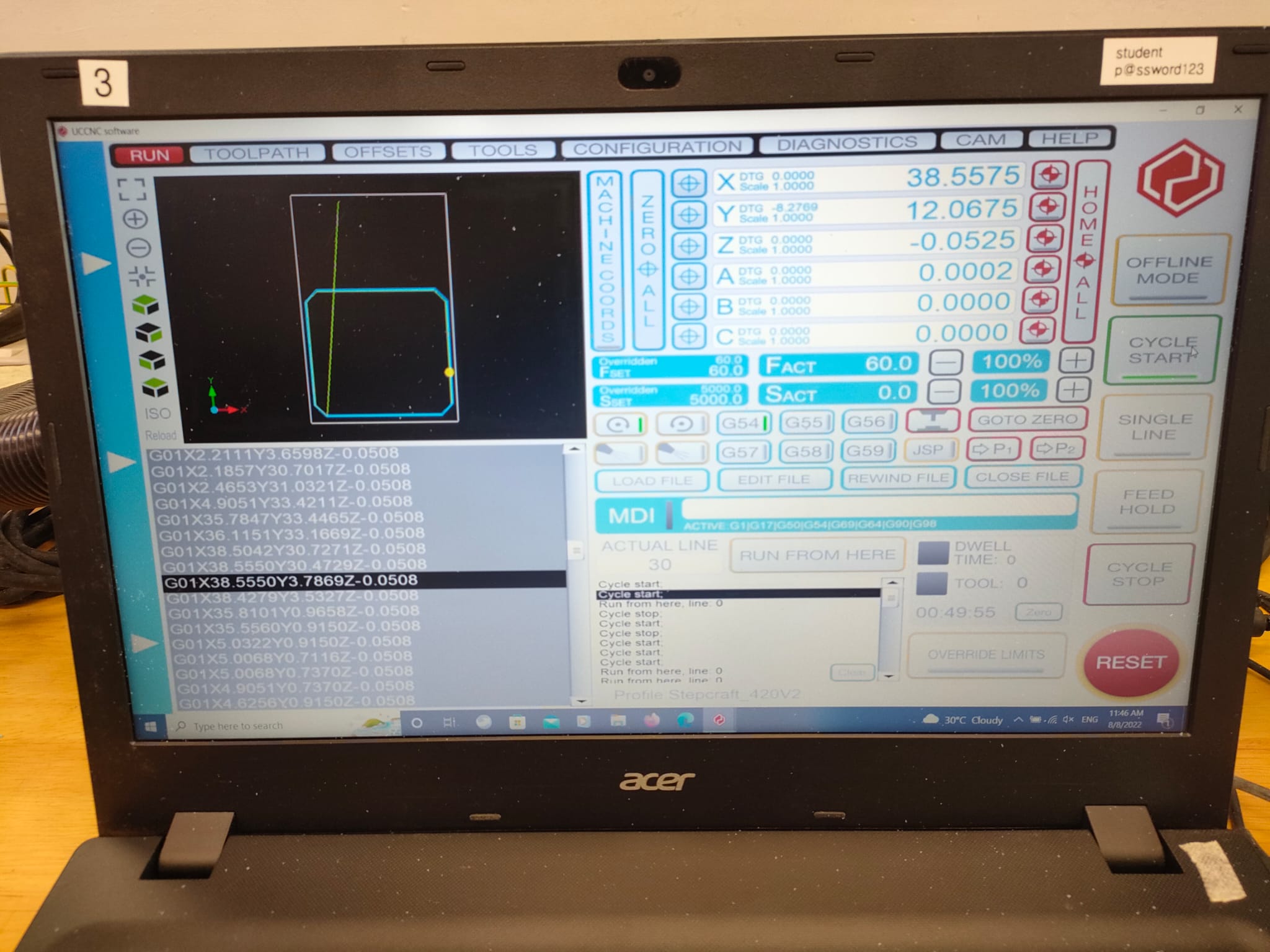
Video |
| Completed PCB board. I have to sand off the sharp edges | 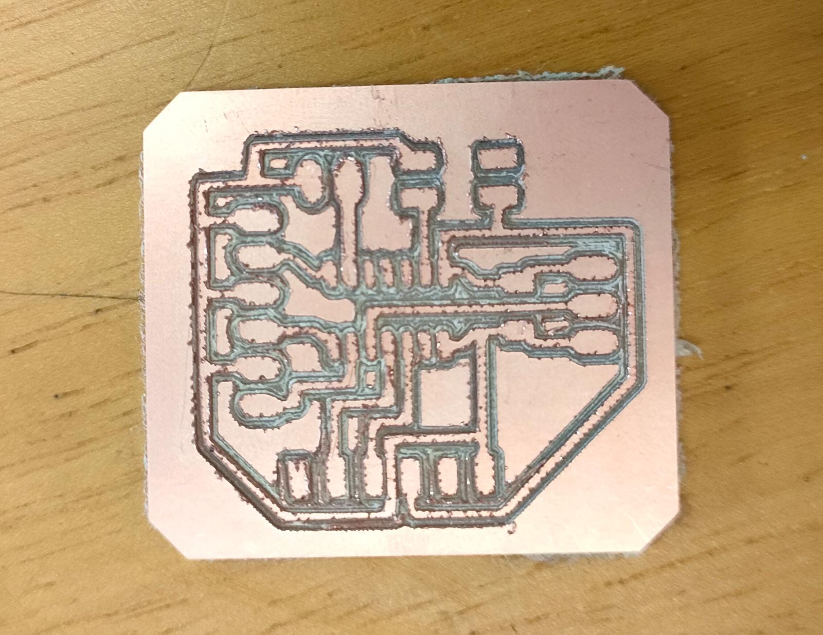 |
After cutting the PCB I can move on to soldering the components.
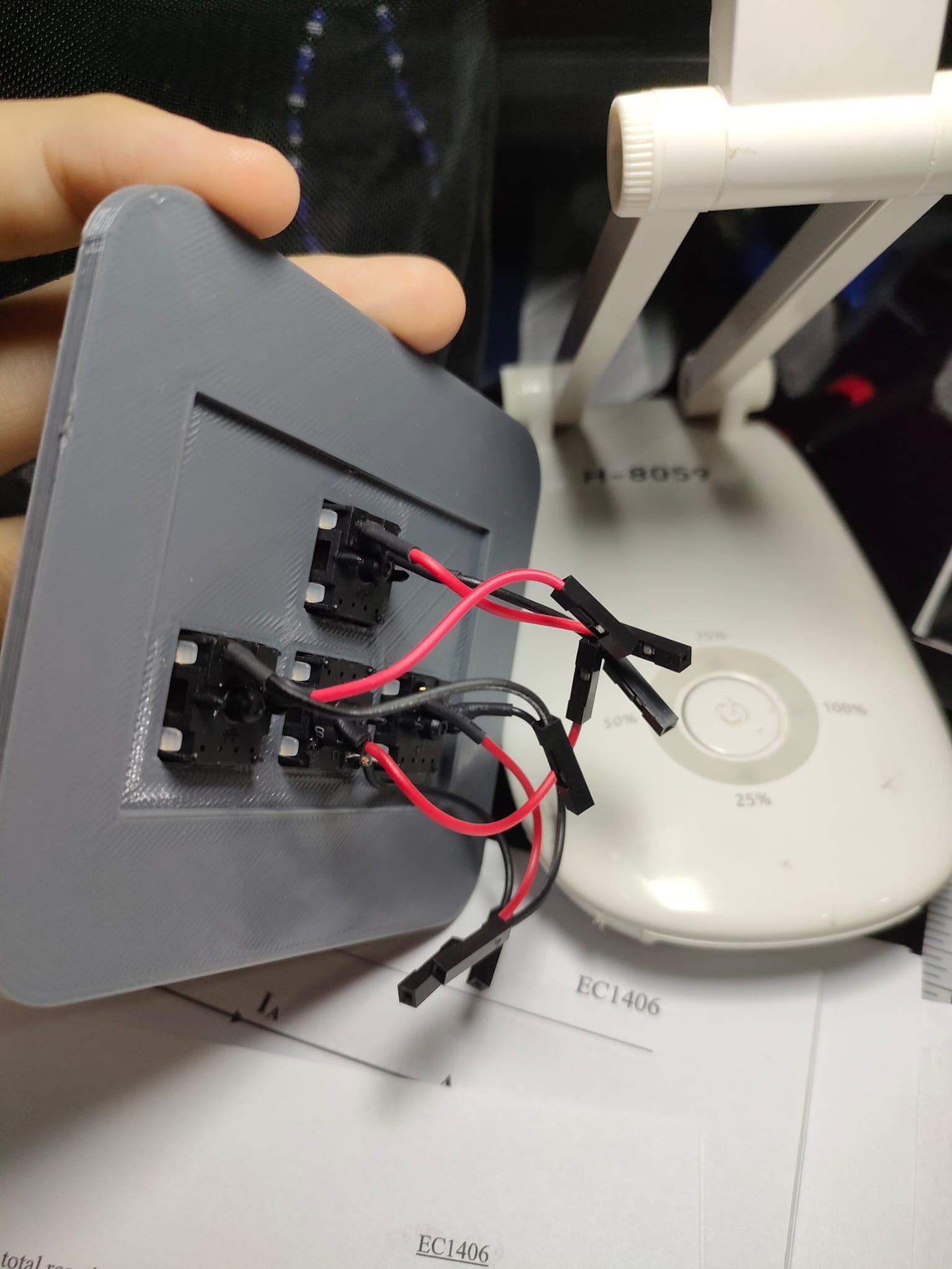
| Switches | 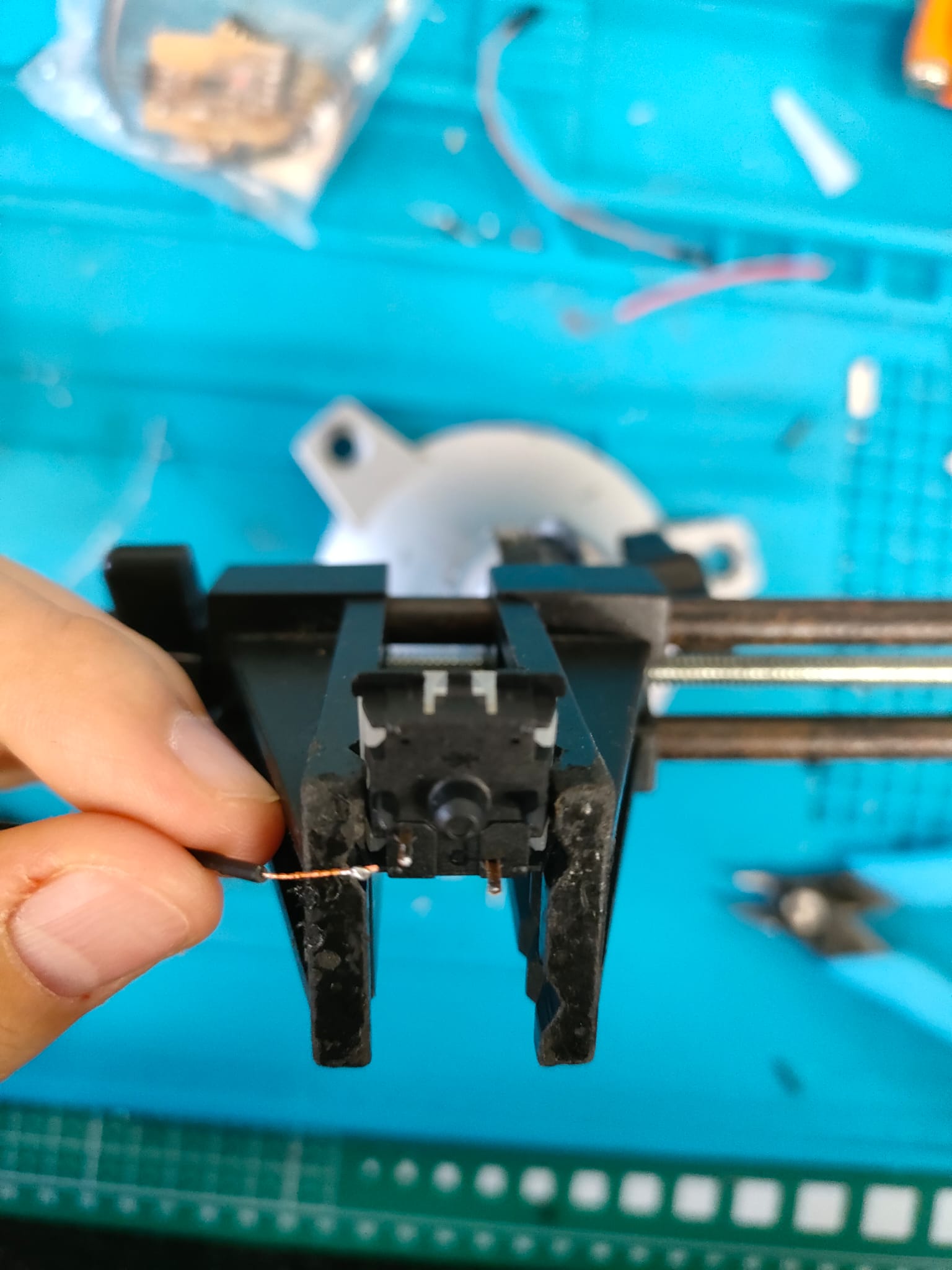
Adding the heat shrink will help secure the wires to the switches better 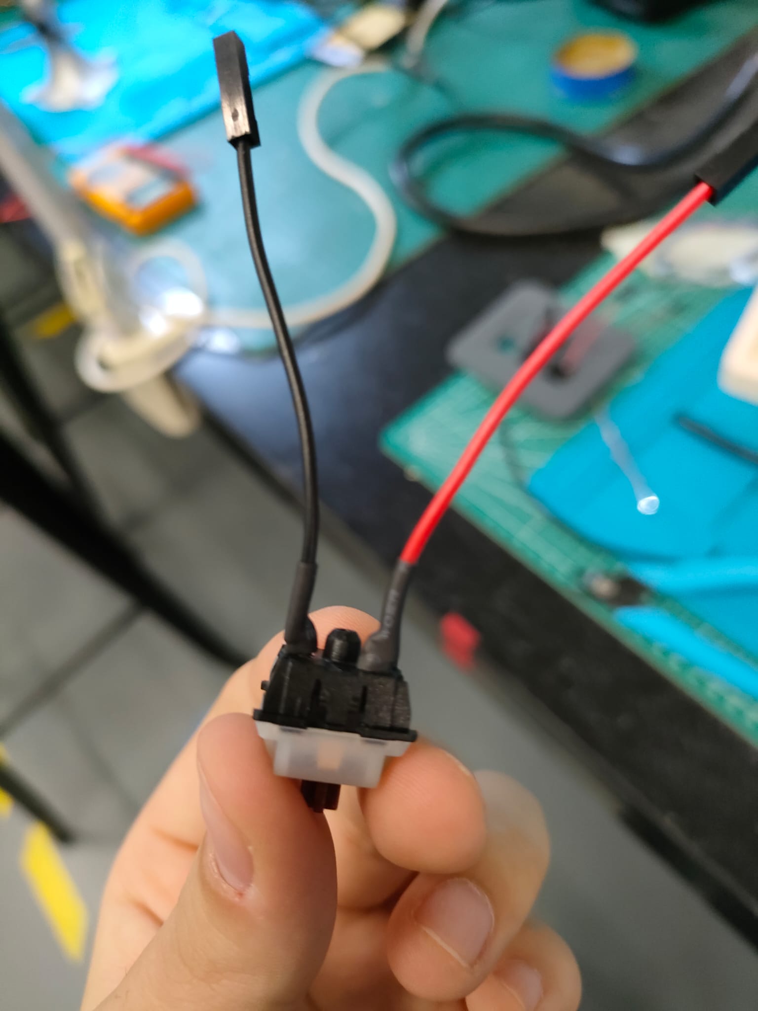 |
|---|---|
| Headers, chips and components | 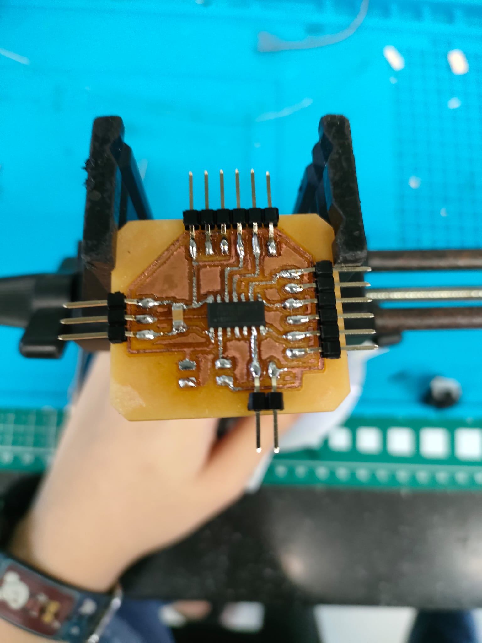 |
| Finish soldering | 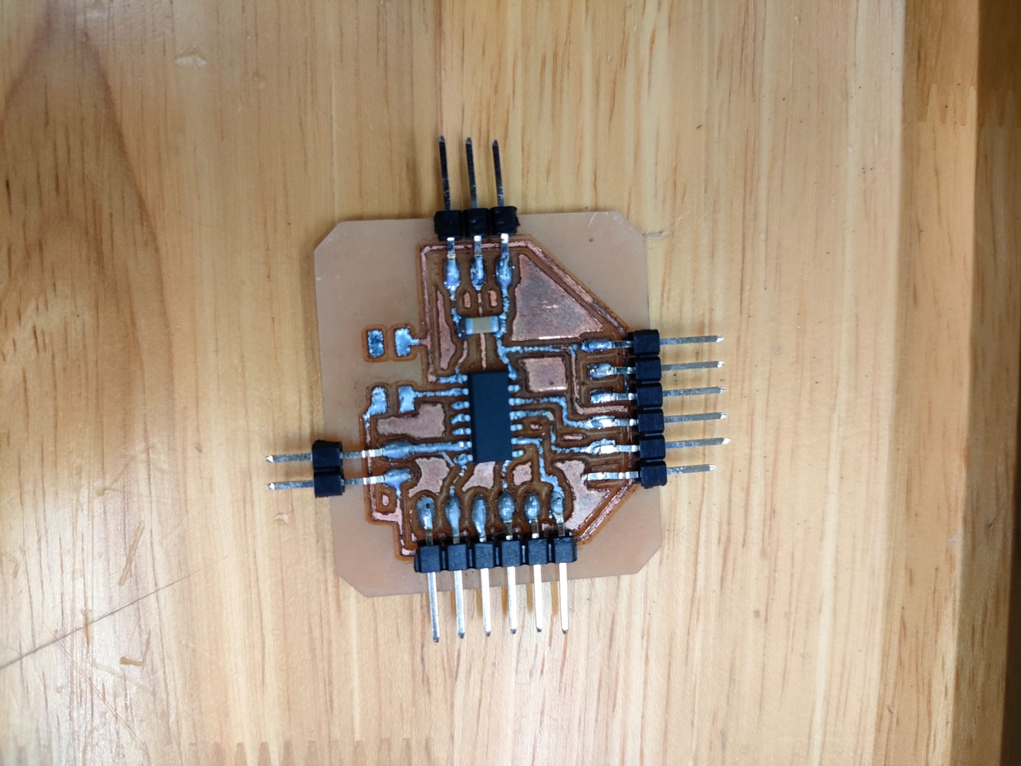 |
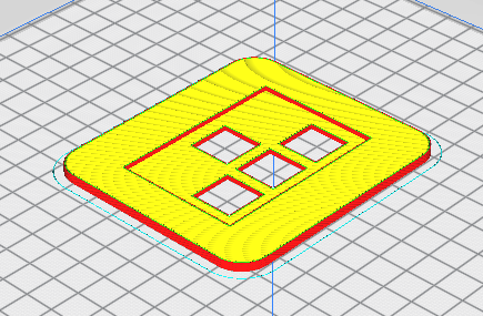
I use fusion360 to desgin my case and cover. For the case it will be 2D Machine and the cover will be 3D printed
Below are the parameters
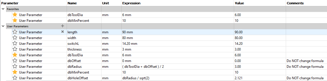
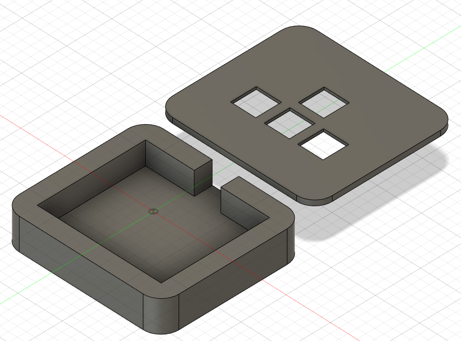
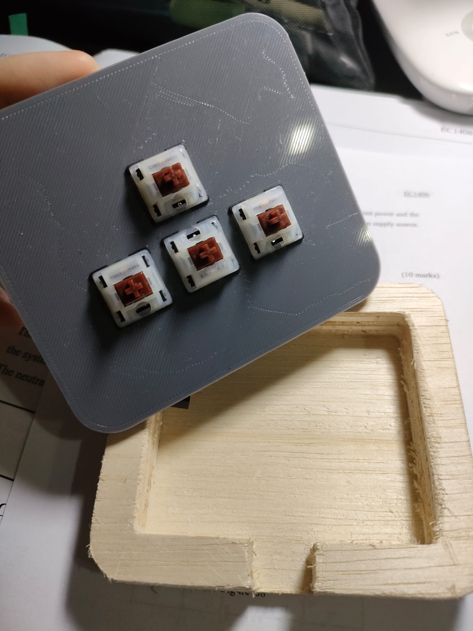
The cover is 90x80x3mm. After measuring my switches I set the keyslot to 14.20mm and 4.8mm apart
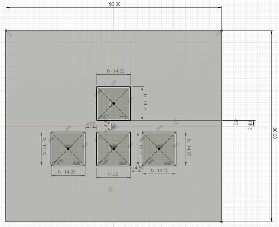
I added extra 1.50mm space incase I measure the height wrongly
The case is 90x80x18mm and a thickness of 10mm. The 15x13mm slot is where the wires for the ftdi will go.
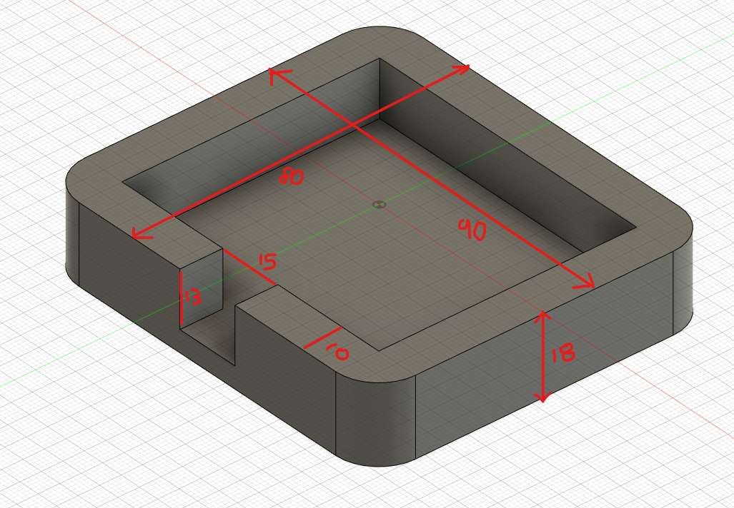
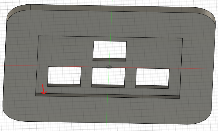
The complete case and cover
You can view 2D Machining on how to set up the machine
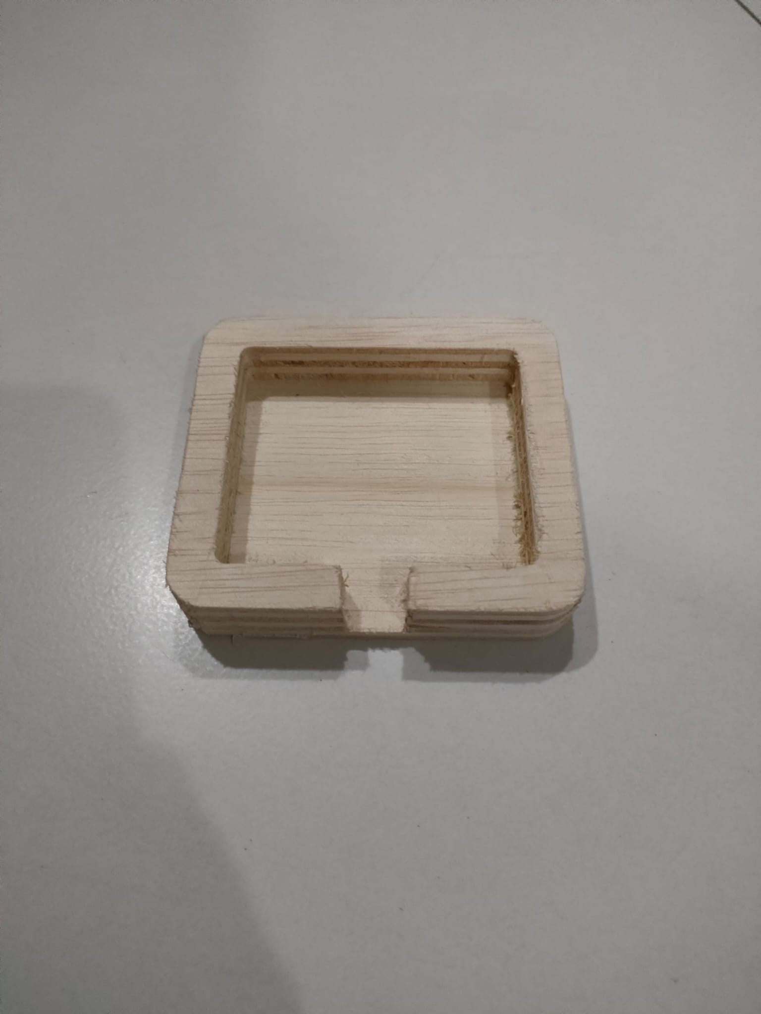
After removing it I still have to sand the sides so that it will not be very rough
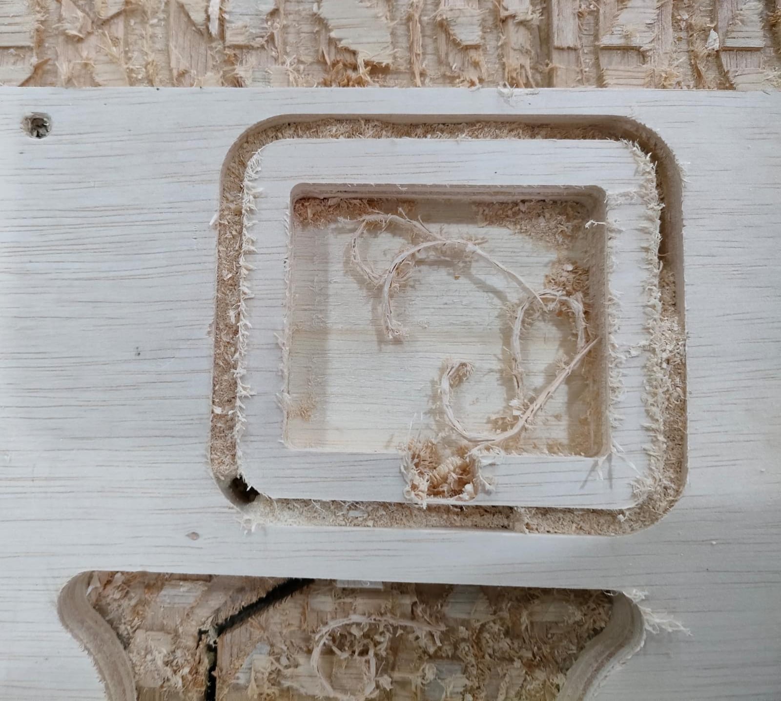
Completed case
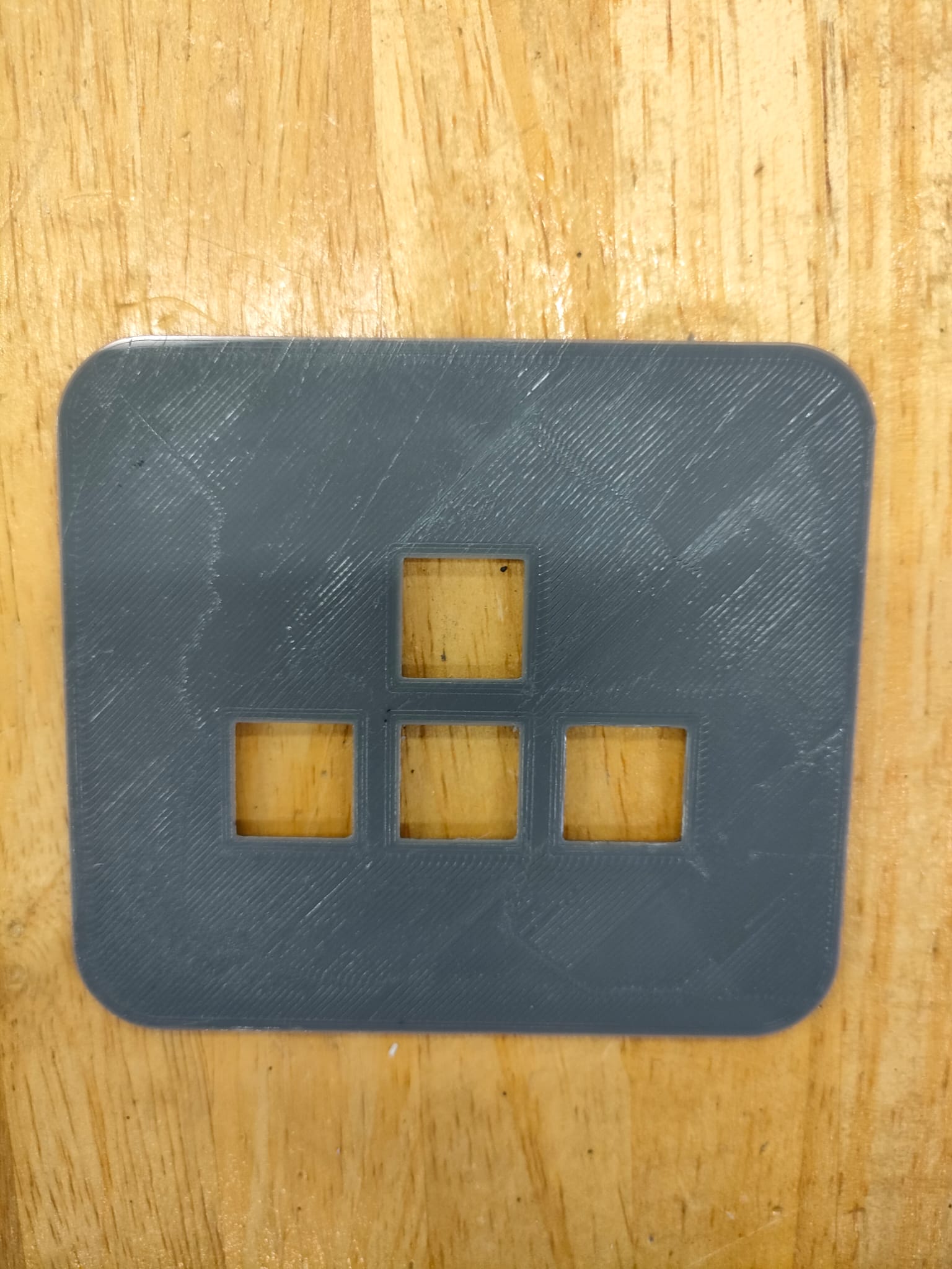
I use the Ultimaker to print the cover
| Setting | Infomation |
|---|---|
| Layer Height | 0.25mm |
| Infill Density | 10% |
| Infill Pattern | Grid |
| Speed | 80mm/s |
| Support | Yes |
| Build Plate Adhesion | Skirt |
Time taken to print: 53min
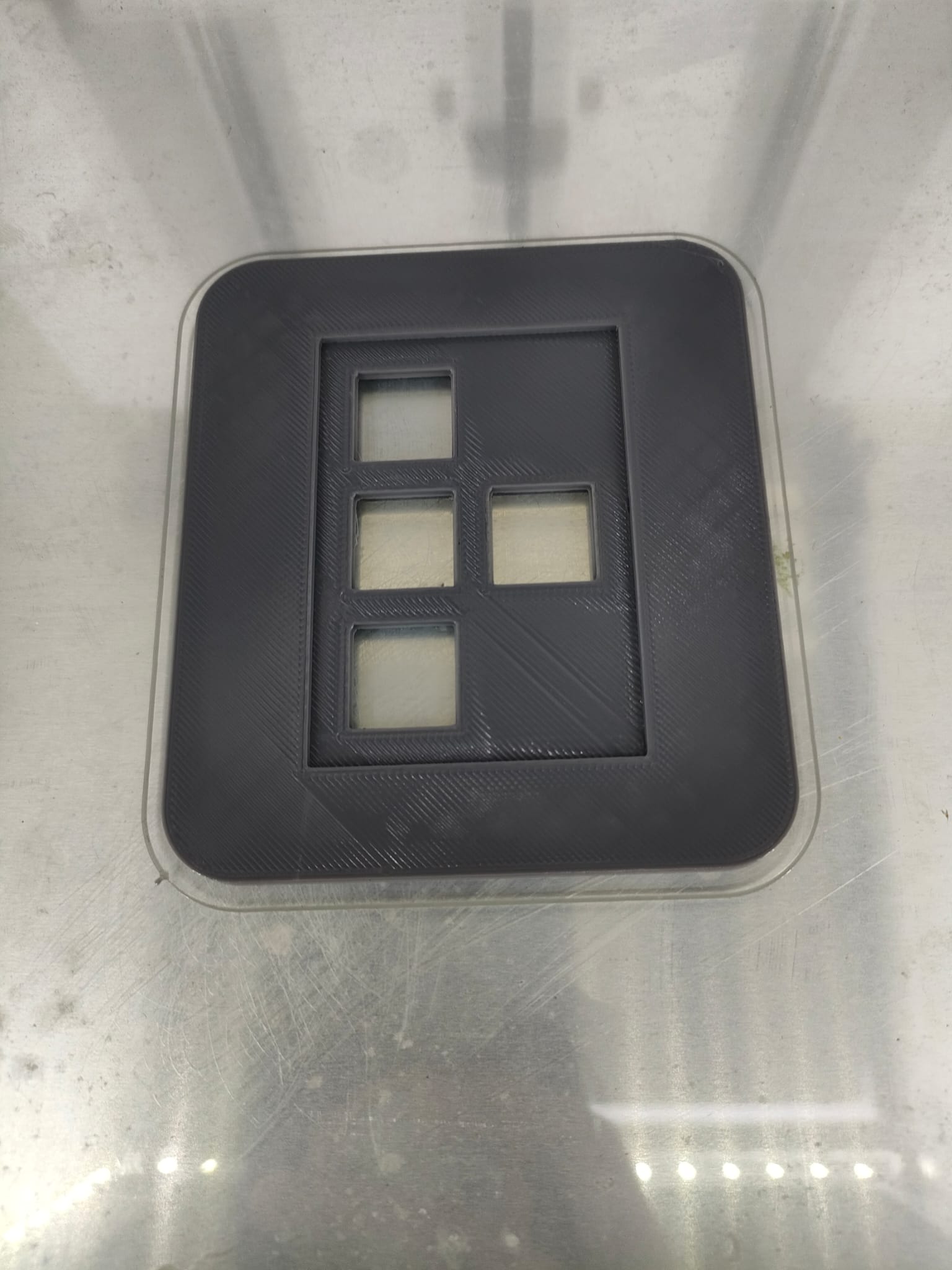
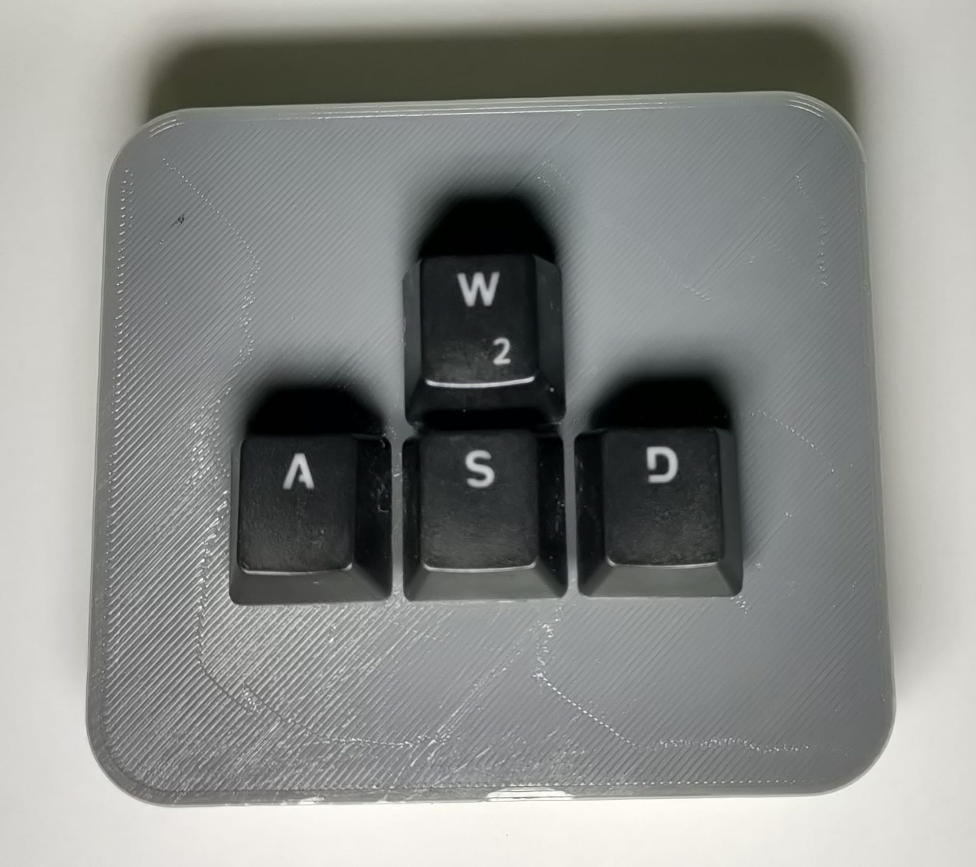
Top view
Because I didnt include a USB port I will have to code both arduino and python
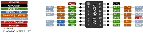
| Attiny1614 (Port pin): | Arduino (Analog/Digital): |
|---|---|
| PB3 | 4 (switch4) |
| PB2 | 5 (switch1) |
| PB1 | 6 (switch2) |
| PB0 | 7 (switch3) |
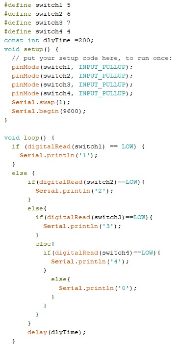
How does the code work?
| 1. #define: Used to define the switches to the 2. const int dlyTime: is use to set a delay for 200ms 3. In the void setup() we need to have a INPUT_PULLUP for each switch as in my PCB there is no resistor. 4. Serial.swap(1) is included because my TXD and RXD is swap 5. Serial begain(9600) also have to be included. 6. In the void loop() it was coded in a way that if switch1 == LOW than Serial.printIn('1') else it will read the other switches and Serial.printIn the correct number base on what switch is being read. 7. If no switch is being read, Serial.printIn('0') 8. At the end a delay is being used |
 |
|---|
Testing if my switches can be sense
 |
|---|
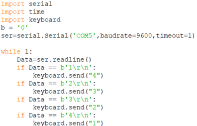
| 1. First import serial, time and keyboard 2. initialize b = '0' 3. Depending on which COM port we using, put them accordingly for this case I am useing COM5 4. while 1, it will read the line which will then be initialize into Data 5. Depending on the Data the correct key will be send to the keyboard 6. In the arduino code above when switch1 is LOW it print line '1' so in the python it will send 4 to the keyboard |
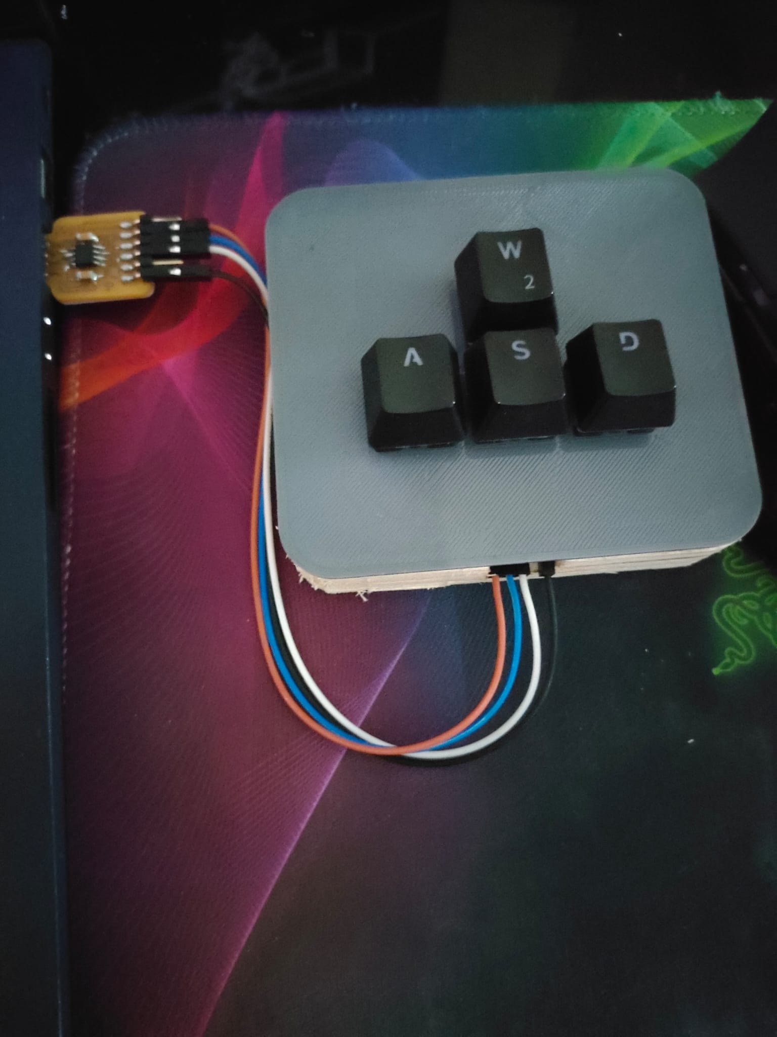
After coding, I assemble my switches to the cover than connect the switches to the PCB board To upload the code to the chip I can use the UPDI and FTDI . After uploading to the chip, I remove my UPDI and open command prompt. First I have to do pip install pynput for my keys to work than I have to locate where my python code is and copy and paste into the command prompt. After that I just have to type python (file) to activate my keys


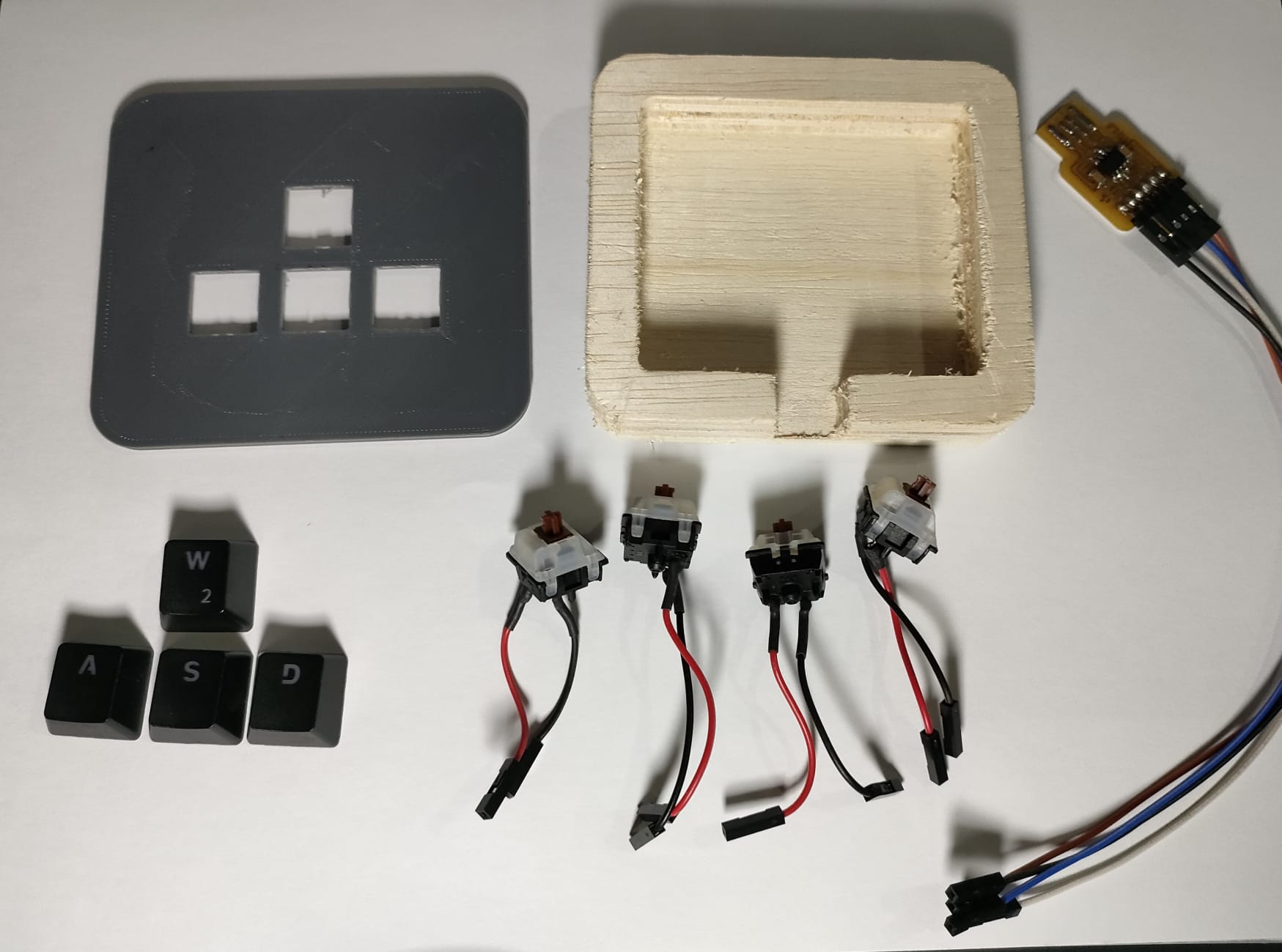
All Parts: Case, Cover, Switches, FTDI board and keycaps
Assemble the switches to the cover
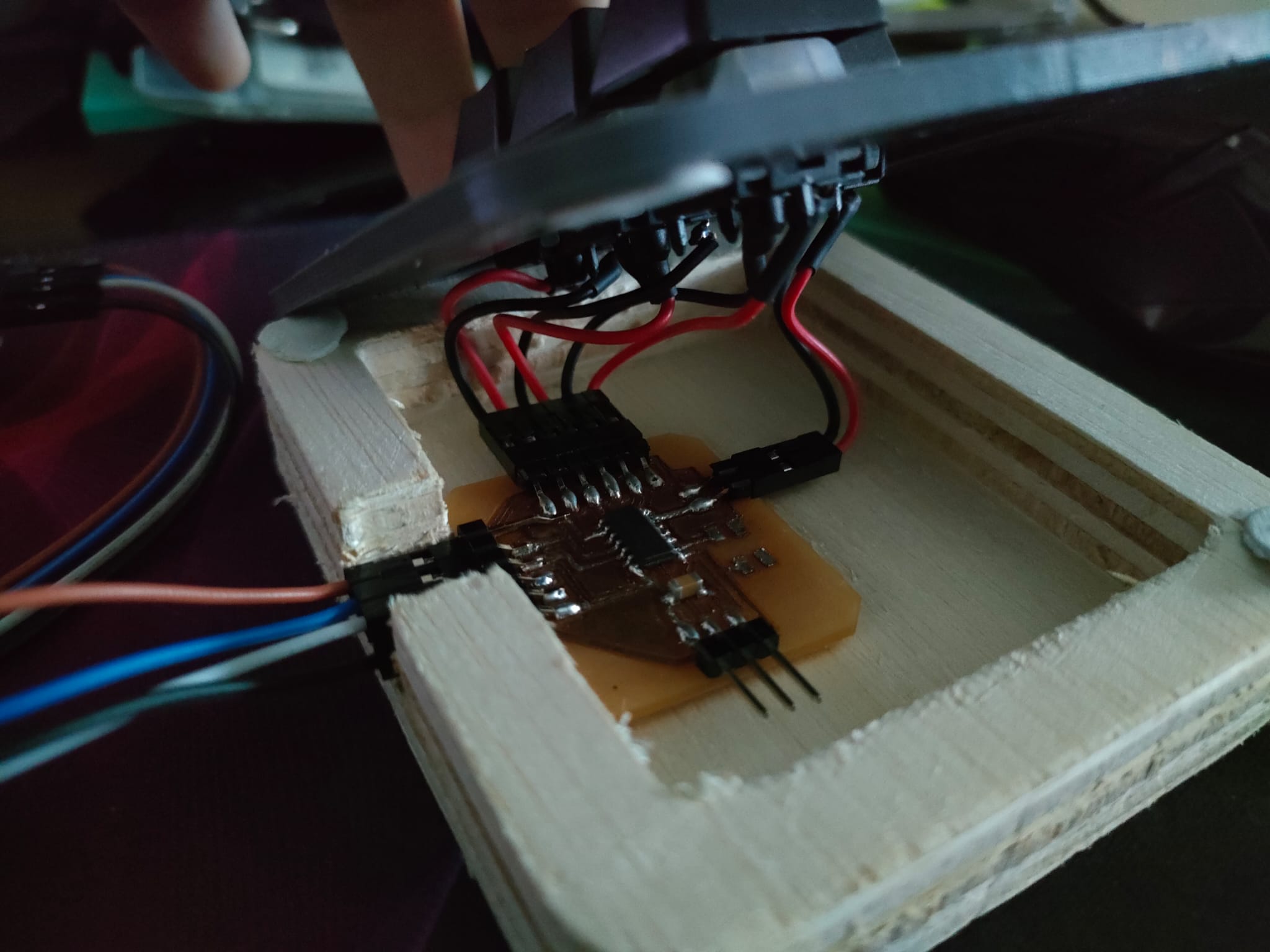
Securing the PCB to the case
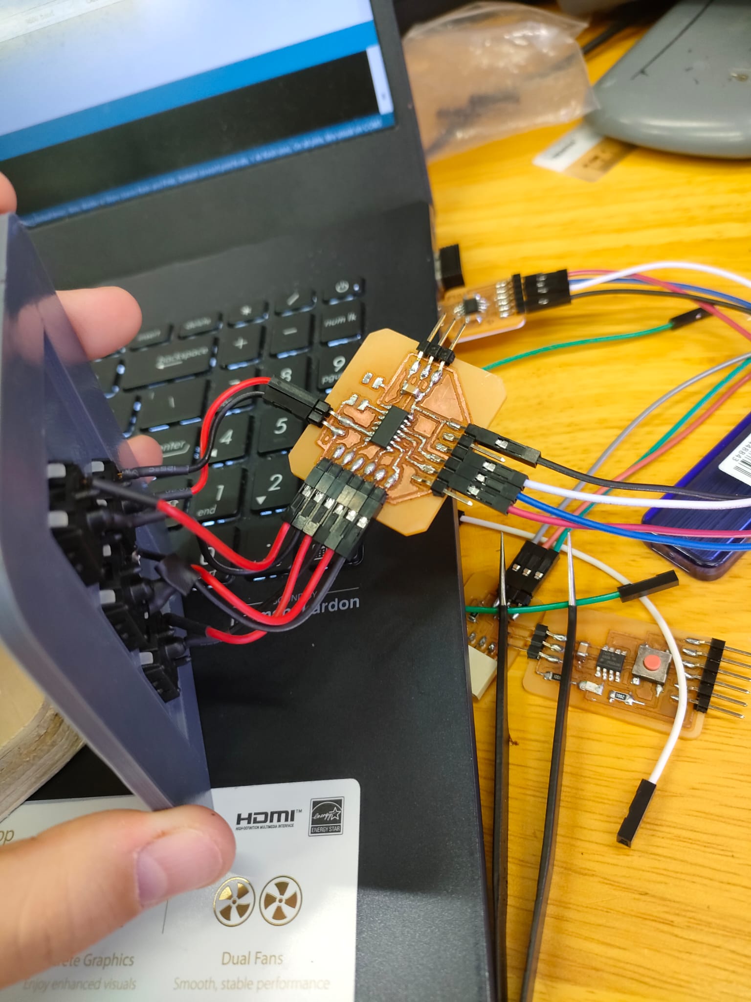
Connect to my laptop
Explaining on how the Product works:
Slides
1min Video
Programming files and Fusion360: Click here to download files.